[archaeological] geophysical techniques
Table of Contents
earth resistivity

Earth Resistivity Logger. John Becker. EPE. Everyday Practical Electronics. April/May 2003
magnetometers
jam-jar/reflective beam

From: Scientific American: Taking the Earth's Magnetic Pulse [January 1999]
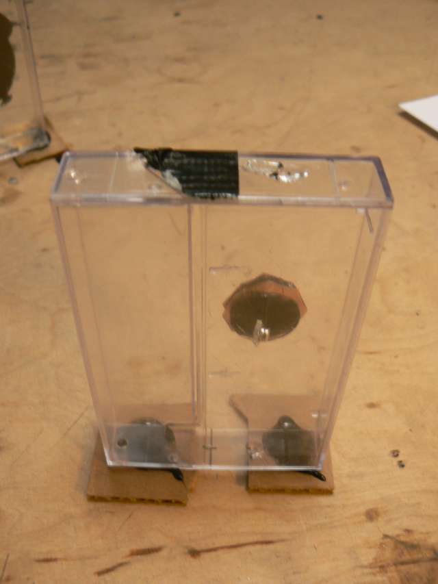
HOWTO for torsion balance cassette box magnetometer:
following MAKE magazine: http://www.make-digital.com/make/vol08/?pg=47#pg47
and Shawn Carlson in Amateur Scientist January 1999.
with a few changes (cassette case, some tech changes):
1] Separate out tiny polypropylene strands from a thicker cord (bought at OBI)
2] Drill holes (0.8mm) in exact centre top and bottom of clear cassette case. Thread tiny strand into tiny needle and thread this through bottom hole and then top. Gaffer tape top thread and place cassette box so that lower part of thread hangs in free space. Make the thread taut by taping several coins to this lower part, and glue both ends of the strand with epoxy.

3] Glue a small mirror to one tiny magnet (4x1mm neodym). With tweezers sandwich the thread between mirrored magnet with another small magnet.
4] Hotglue a small piece of copper behind the magnet to damp oscillations (inducing eddy currents in the copper when the magnet moves and thus an opposing magnetic field).
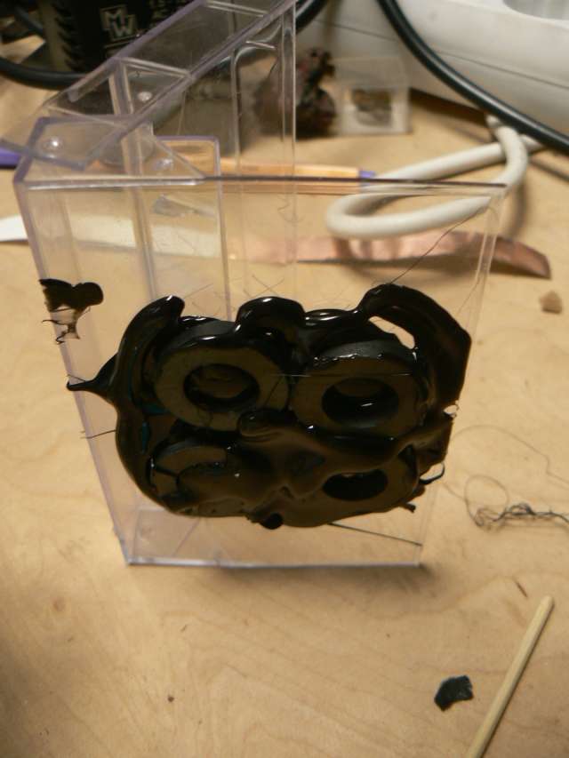
5] Construct a set of nulling magnets by hotgluing four ferrite ring magnets (23x13x5) to another cassette box. Polarity should be observed so the magnets shoyuld repel each other and will need to be held in place while the hotglue dries! These should be centred to align with the magnetometer mirror.
6] See nulling location notes below (question: how critical is alignment of nulling magnets vertically with centre of mirror?)
- location of components/nulling magnets
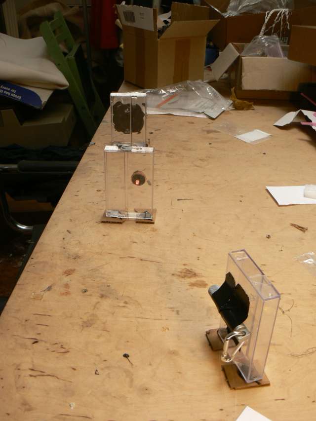
from: http://xtrsystems.com/magnetometer/layout.html
Actually, I find that the balance, laser, and detector can be oriented in just about any direction but the nulling magnet assembly is often best located on the North-South line relative to the balance. The nulling magnet assembly can be translated along this line and can be rotated to provide suitable alignment. Alignment is achieved when the bright red spot of the laser diode falls upon the center of the detector and the lengthening of the period of oscillation occurs as described in the article. However, the nulling magnet assembly does not have to be located to the North of the balance; it can be located to the South but it will have to be rotated by 180° for proper operation.
It is worth repeating that the nulling magnet assembly must be located on the North-South line relative to the balance. If you find that the assembly's optimum position lies elsewhere then it is likely that there is a significant perturbation in the earth's magnetic field due to some local ferrous material. Moving the system to another location is advisable under these circumstances as there is likely to be considerable interference with the real terrestrial signal.
Links:
http://www.regulusastro.com/regulus/papers/magnetometer/index.html
http://www.britastro.org/aurora/jamjar.htm
http://www.eaas.co.uk/news/magnetometer.html
http://www.backyardastronomy.net/compass_magnetometer.html
http://www.carnicom.com/mag2.htm
Compass Detector (compass, led, phototransistor and coil): http://www.dcs.lancs.ac.uk/iono/aurorawatch/detectors/compass.html
MAKE: http://www.make-digital.com/make/vol08/?pg=47#pg47
Torsion balance and coils: http://xtrsystems.com/magnetometer/layout.html
Travel magnetometer in a cassette box:
http://www.astro.uni-bonn.de/~kbagschi/magnet-e.html
Links: http://www.sas.org/E-Bulletin/2004-04-02/wanderings/body.html
fluxgate magnetometer
- FGM-3:

From notes:
with scrying platform/ATmega128 functioning as frequency counter. The FGM-3 [Fluxgate Magnetometer] sensor outputs frequencies between approximately 120 kHz and 50 kHz.
"The Fluxgate magnetometer's sensor uses ferrite ring core driven beyond magnetic saturation with about 10 kHz sine wave drive current. The sensor's output coil is tuned to the second harmonic with a resonant capacitor. The surrounding (geo)magnetic field effects as a bias factor making the output signal (saturation) to become unsymmetric, reacting to variations of the external magnetic field in the axis for which it is sensitive to."
"The idea of a flux gate is that when the core is saturated it essentially disappears and when it's out of saturation it bends the earth's magnetic field lines which cross the coil. The switching of the core in and out of saturation is gating the earth's magnetic filed through the coil thus generating a voltage according to Faraday's law."
[from links below]
Also from Bill Speake:
"I can tell you that the operation of the FGM-3 (and others in the range) Magnetic Field sensor is based on flux-gate principles using modern materials. However it is not a true flux-gate."
Data
Data sheet: http://www.speakesensors.com/PDF/detail.pdf
Pins (reading downwards from top) from back with all pins closest to right): 0 F/B, 1 GND, 2 OUT, 3 +5V

Code:
Which also demonstrates use of counter and INT0 interrupt on pin 25 of the ATmega128 [pin18 on scrying connector].
http://scrying.svn.sourceforge.net/viewvc/scrying/freqcounttest.c?view=markup
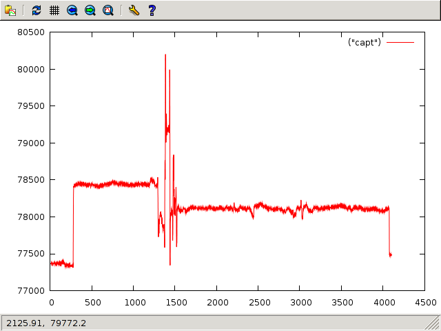
Plot:
Links/references:
PIC Magnetometry Logger. John Becker. EPE. Everyday Practical Electronics. July/August 2004
http://homepage.ntlworld.com/clarcana/proj/magnetometer/index.html
http://www.speakesensors.com/products.htm
http://www.picotech.com/experiments/earths-magnetic-field/
http://www.directivesystems.com/PDF/MAGTALK.PDF
http://www.ursa.fi/ursa/jaostot/revontulet/magnet/enmagnet.html
http://www.prc68.com/I/Sensors.shtml#Fluxgate
http://www.thunting.com/geotech/forums/showthread.php?t=13732
http://ourworld.compuserve.com/homepages/demerson/magnet.htm
http://geotech.thunting.com/cgi-bin/pages/common/index.pl?page=mag&file=projects.dat
thermal dependency of FGM-3: http://www.tuc.nrao.edu/~demerson/cs/Thermplt.htm
proton precession magnetometer

From: Seeing Beneath the Soil. Anthony Clark. 1990
- Scientific American: Building a Sensitive Magnetometer … [February 1969]

- Dan's Homegrown Proton Precession Magnetometer Page:
http://gerf.org/~jasegler/proton_mag/proton.htm
What is the frequency of switching on DC? 5 seconds on/off
0.6->0.8mm diameter copper wire
- further links:
http://www.exstrom.com/magnum.html#node_toc
http://www.ilotresor.com/prospection/pro_magn_protons.html
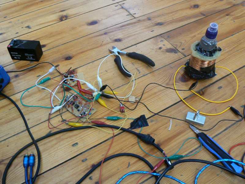
construction notes


Constructed after:
http://www.ilotresor.com/prospection/pro_magn_protons.html
water bottle as pictured (dimensions). 10 layers of 0.65mm wire
rough tests with frequency generator show working filter (to be tested again)
problems
- hum in amplifier when polarizing supply is applied (what is this frequency?)
- noise only (radio) when switched to amplifier
to test
- test outside in countryside
- re-test amplifier
- add resonating cap (2200 Hz - should be 2100 Hz for Berlin) - equation?
update
Redesigned board to eliminate self oscillations:

See: http://1010.co.uk/proton1.tar.gz for schematic and PCB design based on: http://www.ilotresor.com/prospection/pro_magn_protons.html
2nd update/report Mon Oct 4 2010
- notes on testing in Peenemuende
Lots of harmonics (50Hz ??? 180Hz) but with energy around 2100 Hz indicating filter is working. Should be tested now 1M OFF the GROUND
- what is humming when not attached? (switching circuit seems to amplify
or exaggerate mains 50Hz)
- use distilled water or vodka rather than tap water!
- use of tuning cap(value? - see below)
- testing all stages of the ilotresor design
Pre-amp -> passband filter -> headphone amp
Pre-amp and headphone amp (both based on 2n2222) not working for some reason. Pre-amp replaced with op37 based design based on "Practical Guidelines for building a Magnetometer for Hobbyists" (Bayot) and "Construction of a Proton Magnetometer" (Ruhunisiri and Jayananda).
Pre-amp tested successfully with signal generator (100mV signal through 100K/10R voltage divider) and with filter (as per ilotresor design). Headphone amp replaced with LM386 design. Gain of first two stages for 2100 Hz= 50 dB (10logVout/Vin). Filter also working. Possible self-oscillations could be due to external noise.
- measuring induction of the coil
In order to determine suitable tuning cap which will sit across the front end of the pre-amp (signal/GND).
Set up circuit with function generator connected by way of 1K resistor to oscilloscope. Known capacitor (100nF) and the coil are connected across the scope input (so between end of 1K and GND).
Step through frequencies for function generator (100mV pp) say 1-4KHz and look to see where signal peaks. Capacitance must be higher to bring down resonant frequency.
L (Inductance in Henries) = 1/[C(Farads)*(2PI*F(HZ))^2]
In this case for our coil 22mH.
Required capacitance C=10^9/(0.03948*2100^2*22) = 261 nF
Where 2100 is our precession frequency and 22 is mH for our measured coil inductance. Successfully tested with scope/generator and 269 nF caps.
- TODO
- test in the field, 1m above ground and with new fluids (distilled
water, vodka).
further notes
- precession frequency Berlin = 2102 Hz
(49,395 nT x 0.04256)
from: PracticalBuildingGuidelines.pdf
The two coils are wound in opposite directions with respect to each other and connected in series. They are mounted parallel to each other so that external magnetic field noise common to both coils is cancelled out. The signal from the sample in one of the coils can then be detected with minimal interference. Both coils are large enough to accomodate a 2.0 ounce (59 ml) bottle containing the sample.
light
PMT photomultiplier tubes
notes on use of BURLE 4526A PMT with pre-amp assembly

Data sheet: http://www.burle.com/cgi/byteserver.pl/pdf/4526a.pdf
Photomultiplier handbook: http://psec.uchicago.edu/links/Photomultiplier_Handbook.pdf
photodiodes/phototransistors
TSL257 light to voltage convertor
references
Seeing Beneath the Soil. Anthony Clark. 1990
http://water.usgs.gov/ogw/bgas/surface/
Archaeological Geophysics Page: http://www2.prestel.co.uk/aspen/sussex/geophysics.html
Date: 2010-10-04 19:31:55 BST
HTML generated by org-mode 6.31trans in emacs 23